SOLIDWORKS Toolbox Library Setup and Utilization
Assigning Custom Properties to Toolbox Components Including Material
SOLIDWORKS users can add custom properties to any toolbox component, this can allow companies to track data that’s unique to their organization, this could include manufacturer, ordering information, or component cost. To add these data fields, create a custom property for each piece of information that the user would be interested in tracking. These are not enabled by default and will have to be enabled for each piece of hardware it affects.
Abstract
The goal of this article is to explain the different features and functionality available within Toolbox and how to configure these features.
What is the Toolbox Library?
The Toolbox is a collection of several powerful tools built into SOLIDWORKS; it can increase productivity and decrease the time required to complete a design. The Toolbox contains a vast library of standard hardware components that can easily be dropped into a design at any point. These components can be configured to easily populate Bills of Material with part number descriptions or any other custom information that needs to be easily displayed to the user.
Setting up and using a toolbox can be broken into several distinct steps which are listed below.
Note: When utilizing SOLIDWORKS PDM Standard or PDM Professional, the specific steps will be colored in blue.
- Determining the location Toolbox, stored on a network or locally.
- Installation / Upgrade
- Admin access and settings
- Component Visibility
- Custom properties including any available materials
- Custom components
PDM Standard and PDM Professional are both built to manage SOLIDWORKS Toolbox and its files. It’s encouraged to install the toolbox in the PDM environment and set up the vault to manage the files within Toolbox. Details on how to do this can be found in Migrating Toolbox files to a network location or PDM Vault.
Toolbox Installation
The SOLIDWORKS toolbox is installed with every Professional or Premium version of SOLIDWORKS. There are 2 different parts of the installation that deal with the toolbox.
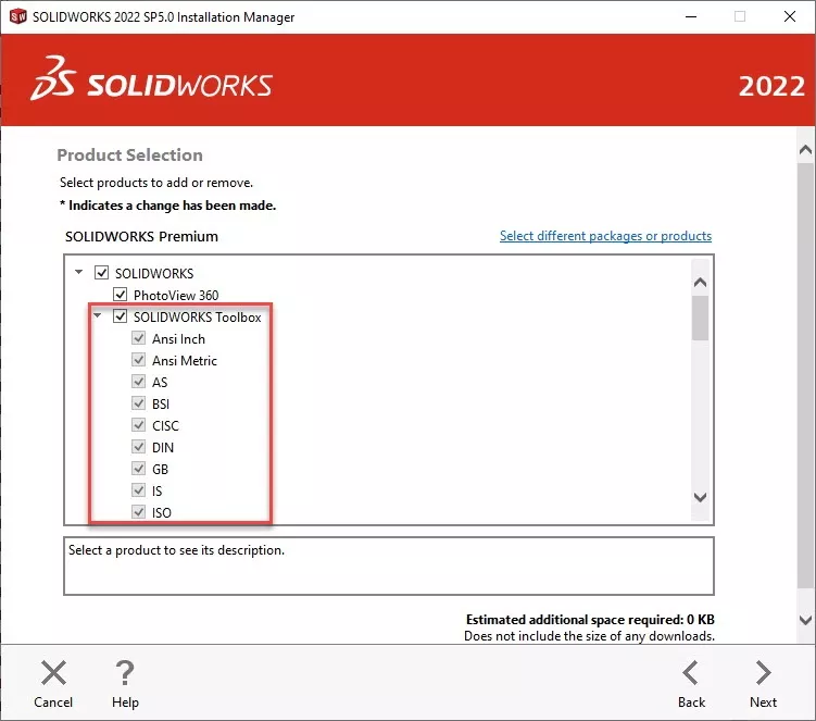
First is encountered in the Product Selection tab, in this window available standards can be excluded from the installation. By default, most users will leave all standards selected.
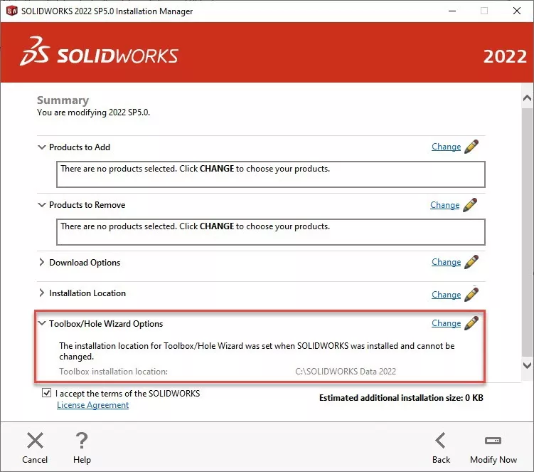
The second part of the installation that pertains to Toolbox is the file location and file name of the toolbox. This is on the “Summary” tab in the installation window. By default, the toolbox is saved to the C:\ drive and it’s named “SOLIDWORKS Data.” Both the location and name of the toolbox folder can be changed by simply selecting change. In the window that follows the user can select “browse” to change location and type in a folder name.
Once the installation of SOLIDWORKS is finished it will include the installation of the SOLIDWORKS Toolbox.
Migrating Toolbox files to a network location or PDM Vault
There is one major deciding factor to determine if moving the toolbox to a network location would be advantageous. If the intent is to customize the toolbox with part numbers, custom properties, or add hardware restrictions a network-based toolbox would likely be beneficial. There are several infrastructure restrictions to having a network-based toolbox. The first is all users will need to have constant access to a network location. This location will also need to have low latency. Any slowdown in data over the network will negatively affect program performance during operations that involve toolbox components.
The first step to migrate the toolbox to a network location or a PDM environment is to locate the toolbox directory that needs to be replicated on all of the user’s machines. The toolbox by default is installed on the computer's C:\ drive typically C:\SOLIDWORKS data. If there are multiple instances of the toolbox the most recent version will have the highest number. This folder along with all of its contents can be copied onto the network drive or PDM vault.
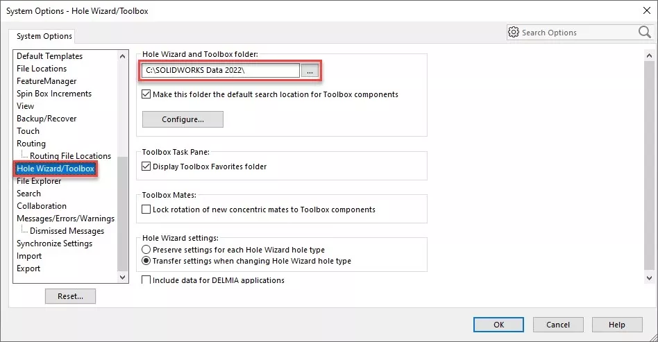
The next step is to configure SOLIDWORKS to use the new location of the toolbox. To edit this navigate to Tools > Options > (tab) System Options > Hole Wizard/ Toolbox.
From here the file location can be changed from the default location on the “C:” drive to the network location. The address can be manually typed or browsed to by selecting the “…”. Once this location has been changed SOLIDWORKS will look to this location for toolbox components.
Note: If using PDM Standard or PDM Professional there are additional steps to finish setting up the toolbox to work with PDM.
After adding the toolbox to the vault, check in the entire file structure. This can be done by selecting the root folder “SOLIDWORKS Data” and selecting “Check in”. This process could take some time since the toolbox contains a large number of files.
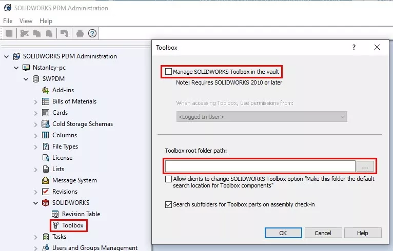
Once the toolbox has been checked in the PDM system has to be configured to manage toolbox components. To configure these settings, open the administration tool and select Toolbox. Select Manage SOLIDWORKS Toolbox in the vault and define the path to the root of the toolbox.
Example: {C:\< Vault-Name>\Solidworks Data}
Once this has been completed see the PDM information in the section Toolbox File Type for information on how to configure settings in the toolbox that will optimize it for use in a PDM environment.
Manually Upgrading Toolbox
When upgrading SOLIDWORKS, it is recommended to use the installer to upgrade the toolbox automatically
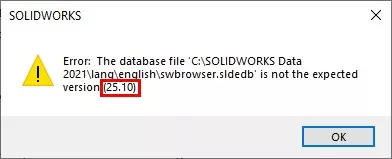
If the automatic upgrade is overlooked or unable to be processed it will result in a version error. This message will not only specify it’s the wrong version but it will specify the version required. The required version will be in parenthesis at the end of the error message. The year is not referenced in the version but the versions are sequential. Version 20 is 2017 so version 21 will be 2018 and so on.
Before upgrading the toolbox, it is recommended that a backup is made. This backup doesn’t have to be complex simply making a copy of the toolbox folder and moving that copy to a safe location will be sufficient. A suggestion is to right-click on the folder and choose Send to > Zip. This will create a zip copy of the folder in its current state. For PDM users this step isn’t required since previous versions of the database are indexed in the vault and can be rolled back.
Now we need to navigate to:
{C:\Program Files\Solidworks Corp\Solidworks\toolbox\data utilities\}
(SolidWorks Corp could be named slightly different, it could have numbers at the end of corp, if so choose the largest number. If the folder was renamed during installation, then it will show by the specified name.)
In this folder find and launch the application: Update browser database.
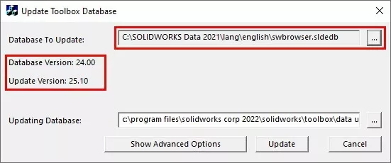
Once in the utility, some information will be provided, and some will need to be selected. First, it will display both the directory to the toolbox and its version. This is loaded from SOLIDWORKS, if this window is blank simply navigate to the database file “swbrowser.sldedb” it exists at \lang\english.
The application will automatically fill out the updating database information. It will reference the folder used to launch the updater from since this folder contains the updating information.
Before using the updater check out the database file swbrowser.sldedb, in the case a file named swbrowser.sldedbold is also found in the directory it will need to be checked out as well.
Run the update utility it’ll take several minutes. Once this is complete the toolbox will be updated. Test functionality by launching the toolbox inside of SOLIDWORKS.
After the update check-in the database and have users get the latest so the changes are reflected for all users.
Toolbox Setup
The toolbox can populate bills of material, contain materials, and automatically be added to assemblies. These functions, though powerful, must be configured by the user(s). Ideally, these would be set up before rollout. As compared to having an incremental implementation.
Permissions
Toolbox contains its own permission structure to limit individual users’ ability to edit specific parameters linked to the toolbox. To activate the toolbox permissions simply create a password and security phrase to lock the toolbox. After this has been created all users wishing to change locked aspects will need the administration code to do so. This limits the users from being able to make changes with unintended consequences.
Each setting has a specific purpose.
- Content: This is what pieces of hardware is available for use in the toolbox add-in within SOLIDWORKS.
- Custom properties: These are set by the user, these could include vendor, material, or various other trackable hardware information.
- Adding: This restricts users from adding custom SOLIDWORKS parts to the toolbox database.
- Part Numbers: This is an included property in each component, this is very similar to its custom property counterpart.
- Editing Configuration names: These are the unique names generated by the program when the hardware is initialized for the first time.
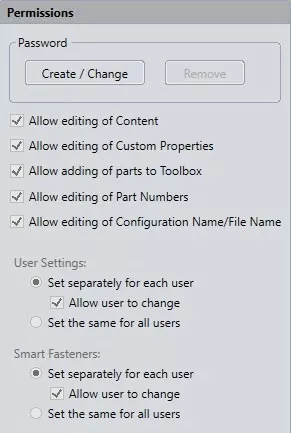
The user settings only control the settings for the toolbox settings program. These options do not pertain to any settings contained within SOLIDWORKS.
Smart fastener settings control what hardware files from the toolbox are used when a user activates the smart fastener feature within SOLIDWORKS. This setting will control if these settings will be companywide or if they can be configured by individual users.
Toolbox settings
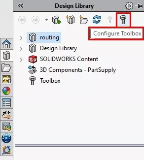
The toolbox has a variety of settings that require configuration for the best utilization of the toolbox program. These control how the toolbox functions internally along with what data will be displayed to the user while they utilize the toolbox inside of SOLIDWORKS. To edit the settings associated with toolbox launch the toolbox settings program (or choose configure toolbox inside of SOLIDWORKS) and select option 3 “Define user settings”.
The first major setting is whether toolbox will create parts or configurations when hardware of a new configuration is used. This is an internal setting and will not change how the user interacts with the toolbox utility.
Create Configurations will add a new configuration to an existing toolbox file each time a new toolbox size is used. This will lead to very large files with a large number of configurations. This setting can see a reduced performance in large assemblies.
Create Parts will create a library of files each file representing a single configuration of a toolbox file with a single specific size. This setting will create a large volume of part files but each of these will have a very small file size.
Create Parts on CTRL-Drag is a hybrid of the two versions previously mentioned, it will act like create configurations except for when users press CTRL while dragging components onto the screen.
If either method that causes the creation of parts is selected. A folder location will need to be defined to have generated part files deposited. SOLIDWORKS has included a blank directory in the SOLIDWORKS Data folder named “Copied parts”, this or any other directory can be defined. It’s recommended to use a directory inside of the toolbox though so that when backups are taken they include all generated toolbox files.
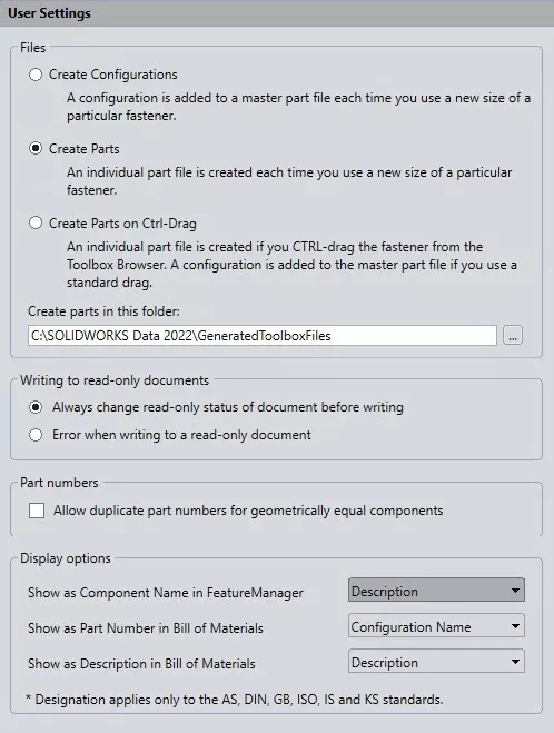
Writing to read-only documents this setting is typically left in its default state, this controls the read-only state of the part files in toolbox. This just gives the program the right to change the read-only flag. If either file setting has create configurations active this setting should be set to allow toolbox to change read-only status.
Part numbers allowing the same part number for geometrically equal components can be useful when a hardware component has several custom properties that generate different configurations even though the component will have identical geometry. This does not allow the user to enter the same part number for non-similar components.
Display options control what information about the hardware is visible to the user and in what context. The variable used is not limited to the standard description, comment & part number. It can be any custom toolbox property defined by the user.
Standard Component Properties
All hardware in the toolbox contains standard properties, the individual properties will vary based on the type of component selected. These properties include all the basic construction data about these pieces of hardware. To view or edit the standard properties choose a component inside of the toolbox and the user will be presented with a window similar to the one below. Below is an explanation of the different properties and what they’re used for.
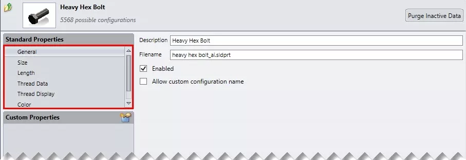
General: The general properties are displayed in the image below it contains the description of the component in the toolbox (Note: this is not the same as the description used in BOM’s within SOLIDWORKS). It will also have the SOLIDWORKS part file that contains the geometry for this part file along with a couple of settings. The enabled setting allows or restricts users the ability to use this component within SOLIDWORKS. Checking “Allow custom configuration name” will unlock the configuration name column lower on this page allowing changes to be made to the configuration names of components.
Size/ Length: The size and length settings control the ability to use particular sizes or lengths of this particular piece of hardware. This allows the toolbox to be edited to match company standards by disabling and or adding sizes that match what hardware is available to the user(s). In this window, it’s also possible to add custom sizes and lengths to the toolbox hardware if there exists a particular size that’s not included by default inside the toolbox.
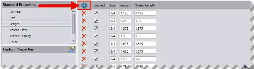
Once the add icon (+) is selected the user will be prompted with a window asking for all the relevant data required to generate this new size or length. Once this data has been entered the new size will populate in the list on the right and will be available to users within SOLIDWORKS.
PDM users will need to get latest on the toolbox database for these changes in sizes or lengths to be available for all users in the vault, to configure this functionality to automatically happen on login see the PDM-specific section in Migrating Toolbox files to a network location or PDM Vault.
Thread Data: This property is very similar to the size and length area of the toolbox, with some minor changes. The user cannot allow or restrict the thread data properties like size and length. Adding custom thread sizes to the toolbox follows the same process as adding sizes and lengths, to use this new thread data the user will also need to also add a new size that calls on the newly added thread data. When adding custom bolt sizes with unique thread data it is recommended that users add new thread data entries vs modifying existing thread data inside the toolbox.
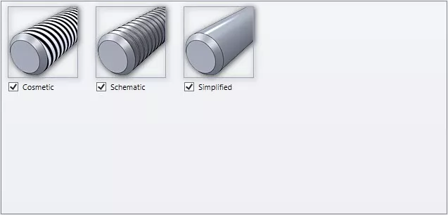
Thread Display: This setting is custom to bolts and won’t be found on other pieces of hardware. This controls the detail the toolbox components contain when included in an assembly. There are 3 options in this setting, from least to most detailed: Simplified, Cosmetic, & Schematic. The thread rendering will have a noticeable performance impact on large assemblies, for best performance use Simplified but for the most realistic appearance use Schematic.
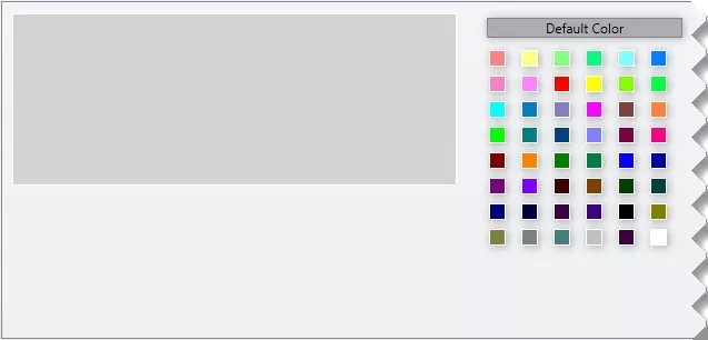
Color: The last setting in the standard properties is color, this can be used to very obviously set the color of a component. Once this setting is opened it will be possible to select a color for the component from one of 48 available with the option to toggle back to the default color above.
Manually Add Components to the Toolbox
Not all custom components manually added to the toolbox will have the same functionality as components that come preinstalled with the tool. If attempting to add a component that’s similar to a component that currently exists in the toolbox, toolbox functionality can be added. An example is a nylon locking hex nut vs a standard hex nut. If the component is entirely unique and in no way similar to any toolbox components this won’t be possible. In this case, the toolbox will have the same functionality as the design library and it is recommended to use the design library instead of adding these components to the toolbox.
Creating Components Similar to Toolbox Hardware
Right-click on the hardware component and select copy, then paste the component into the desired location in the toolbox. Once this has been finished toolbox will generate a new SOLIDWORKS part file for this new component. This part file can be edited to add features to represent the changes in geometry. (locking hex nut example above) A warning when doing this, do not edit the existing features in the part, only add features below the current tree. Using relationships to scale the features is recommended as the features added will need to be valid for all component sizes.
Adding Truly Unique Components to the Toolbox
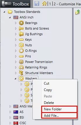
First, all possible configurations for the component need to be prefabricated. Second, each configuration will need its relevant custom properties (IE part number, size, etc.) input into the files.
Once this has been done launch the toolbox settings 20XX program or configure the toolbox. Once here, navigate to the folder in which this custom component should reside. It is possible to create folders as well to contain these custom components. To add a folder simply right-click on the parent folder to contain it and select Add Folder. Once the folder is added/ found simply right-click and choose Add File. This will add the component to the toolbox and allow the user to define custom properties for the newly added component.
Setting Part Numbers, Descriptions, and Comments for Toolbox Components
The toolbox has three default data fields for all hardware components, these are Part numbers, Descriptions, and Comments. These fields are included in all toolboxes and can be populated with information that the user would like to appear in BOM’s associated with an assembly that incorporates toolbox hardware.
There are two different ways to populate this data. A user or admin can either the data manually into the toolbox setting program using the fields included in the toolbox configure window. Or a faster option is the user can export the data to an excel table and populate it using excel or any other third party applications that will work with excel file types.
Manually Entering Data Into Toolbox Settings
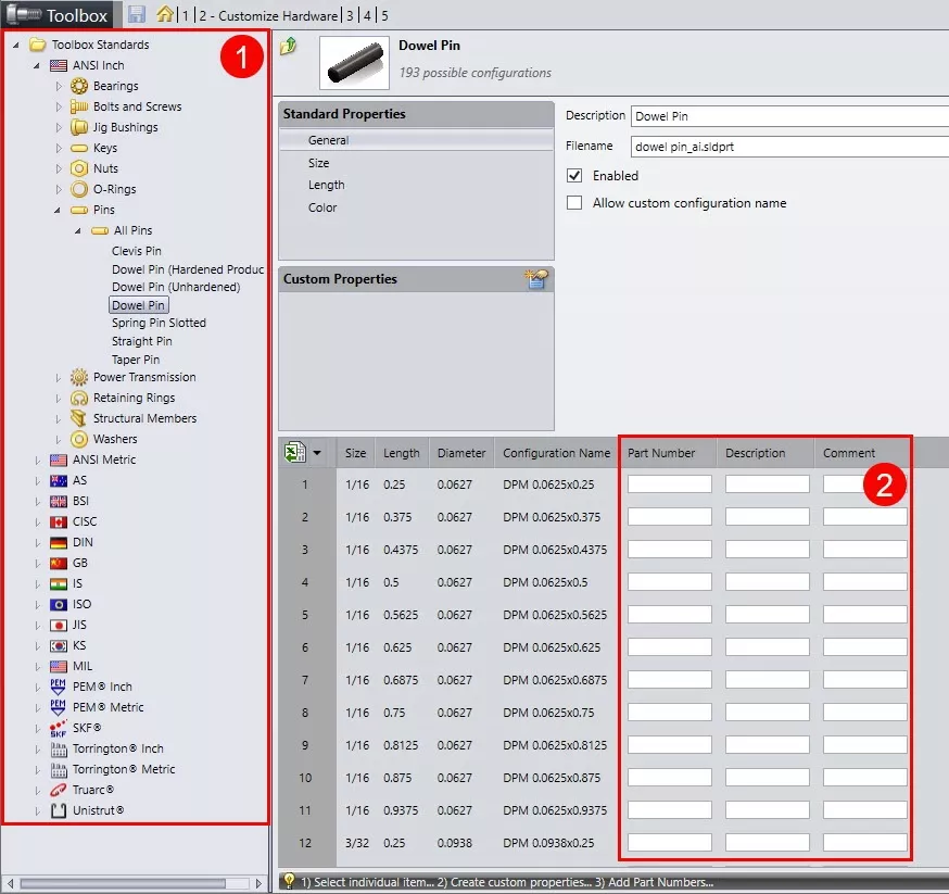
Manually entering data into the toolbox settings program is pretty straightforward, launch the toolbox settings application then open “2-Customize Hardware” Once here entering the data is simply a 2-step process.
- Navigating to the desired piece of hardware in the toolbox settings application.
- Then insert the data into the boxes that are for the hardware specified. There will be a specific row for every configuration of the toolbox component that’s available.
Once this data has been populated the toolbox will need to be saved. Once this has finished the new information will then be available for all users when they insert this hardware into an assembly. PDM users will need to “get lasted” on the toolbox database for these changes to be visible.
Exporting and Importing Data Using Excel or Third Party Applications
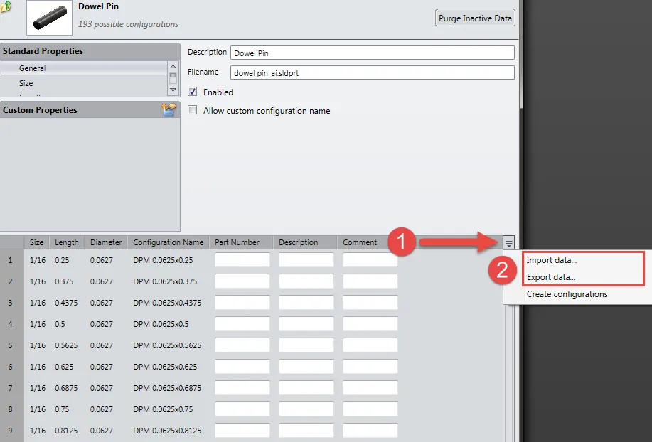
The part numbers and configurations can be exported to an excel file format <.xlsx> this can be then opened in Excel or another application. When entering a large volume of data this approach will be much more efficient. Using this method will require 3 steps.
- Export the template from toolbox.
- Enter data using excel or another application.
- Import the data back into toolbox.
The exported excel document will have several sections, these dictate where information should be stored as well as provide information about the hardware this document is used to specify.
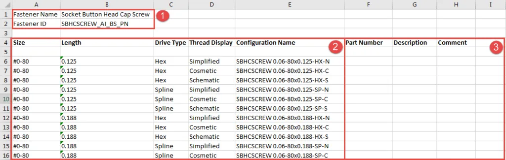
- The first box is the fastener name and ID these are the fields used by toolbox to know what hardware component this data is for. (Do not edit these fields)
- This is the configuration information these are information about the physical dimensions of the hardware sizes (Do not edit these fields)
- This is where properties that can be configured will appear, custom properties will appear alongside the default properties if custom properties are defined for this component.
Note: Adding rows to the excel document will not generate new sizes, to add sizes to the toolbox see the section “Standard Component Properties” for instructions on this. Any custom rows added that do not match existing size data will be excluded during the import.
Once the import is complete the data will appear in the fields of the toolbox settings program. The tool doesn’t maintain a constant link to the excel document. If changes are made to the excel document the excel file will need to be reimported for those changes to be reflected in the toolbox. It is recommended that users keep these excel documents as a backup of the part numbers that have been inserted into the toolbox.
Assigning Custom Properties to Toolbox Components Including Material
Users can add custom properties to any toolbox component, this can allow companies to track data that’s unique to their organization, this could include manufacturer, ordering information, or component cost. To add these data fields, create a custom property for each piece of information that the user would be interested in tracking. These are not enabled by default and will have to be enabled for each piece of hardware it affects.
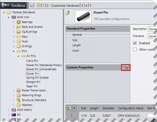
To create a custom property first select the add new custom property icon in the top right corner of the Custom Properties box. Once the icon is selected a dialog box titled Custom Property Definition will open, this box will allow the user to customize the custom property they’re adding or modifying. Below is detailed information about the options included in the definition window.
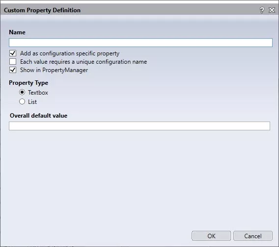
Property Name: This is the variable name the user will see when activating this property for certain components as well as the variable name that will be displayed within SOLIDWORKS above the drop-down or textbox for this property.
Type: When the user inserts this piece of hardware this option will control if the user sees a drop-down or a text box in the toolbox configure component dialog box within SOLIDWORKS. This will control what data is applied to the custom property inside this piece of hardware when dragged into an assembly. This is typically set to list if there’s a finite amount of options for the user to choose from.
Options:
Add as configuration-specific property: This setting will control if this custom property can be unique to each size or if it’s globally applied to all sizes of the component.
Each value for this property requires a new configuration name: This option will create custom configurations for each option in the custom property. This is helpful if creating a custom property such as manufacturers and wanting to populate different part numbers for each manufacturer. If used with a list type property a suffix option will also have to be populated, the suffix will be what’s displayed to the user inside of SOLIDWORKS.
Show in PropertyManager: This will control if this property is shown in the SOLIDWORKS PropertyManager when the component is used.
Assigning Materials to Toolbox Components
Toolbox components can be configured to include material as a custom material allowing the user to choose between different materials for components. Since material isn’t included as a standard hardware criterion it’ll have to be defined as a custom property.
Type: “List”, material selection exists exclusively for list type custom properties. The custom property will then need to be linked to the SOLIDWORKS Material Library. A check box for this will appear after setting the type to list.
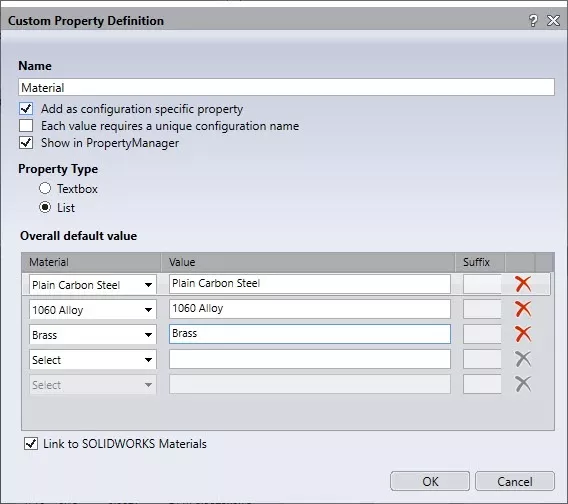
Material/ Value: When the “select” box under Material is selected it will allow the user to select a material from the material library, this will include all custom materials. Once a material is chosen it will need to have a value assigned. The value fields are the fields that will be presented to the user in the drop-down list within SOLIDWORKS. An example of the drop-down within SOLIDWORKS is outlined to the left.
Note: If a unique part number needs to be assigned for each different material the box “Each value for this property requires a new configuration name” will also need to be checked.
Smart Fasteners
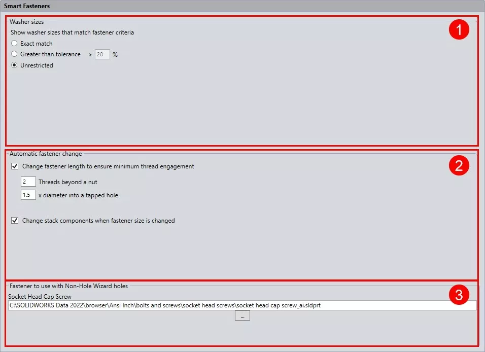
The settings for the smart fastener can also be found in toolbox settings, they’re under option 5 “smart fasteners” This portion will outline the settings found here and how they’ll affect the use of smart fasteners inside SOLIDWORKS. There are three sections to the settings in the smart fasteners menu.
- Washer sizes: This will determine the size of the washer used when inserting washers into a top stack.
- Automatic fastener change: Hardware lengths are automatically calculated when inserting hardware using smart features, these rules dictate the length of those components.
- Non-hole wizard holes: The smart fastener is built to work with hole wizard holes, it’s possible however to manually choose generic holes in an assembly and smart fastener will populate the default fastener listed in this window.
Toolbox Functionality
The toolbox has many different options for adding hardware into assemblies, the two most common methods that will be covered in this manual are drag & drop, along with the use of smart fasteners. Other great methods of adding hardware but ones not covered in this material are the use of toolbox components within smart components, smart features, and the hole series commands.
Enabling Toolbox Add-in
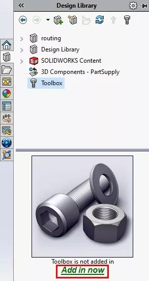
To utilize the toolbox the feature will first need to be enabled inside of Solidworks this can be done on an as needed basis or can be configured to automatically start when the program launches. If configured to launch toolbox on startup Solidworks will require a professional or premium license. The first way to add the toolbox tool is by selecting Add in now when the toolbox window is opened within the design library.
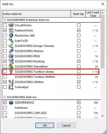
The second method configures if the utility will activate automatically when the software launches. To access this option simply go to Tools > Add-ins or select the dropdown by the settings gear icon and select Add-ins.
From this window locate the toolbox and the checkboxes located on either side of it. The checkbox to the left activates the utility for the current session in the software. The box to the right will trigger the utility when the program launches.
This window also documents the launch time of the utility. So if system performance or launch time is a concern this window can be used to determine if the add-in has a significant impact on the time required to start SOLIDWORKS.
Drag & Drop
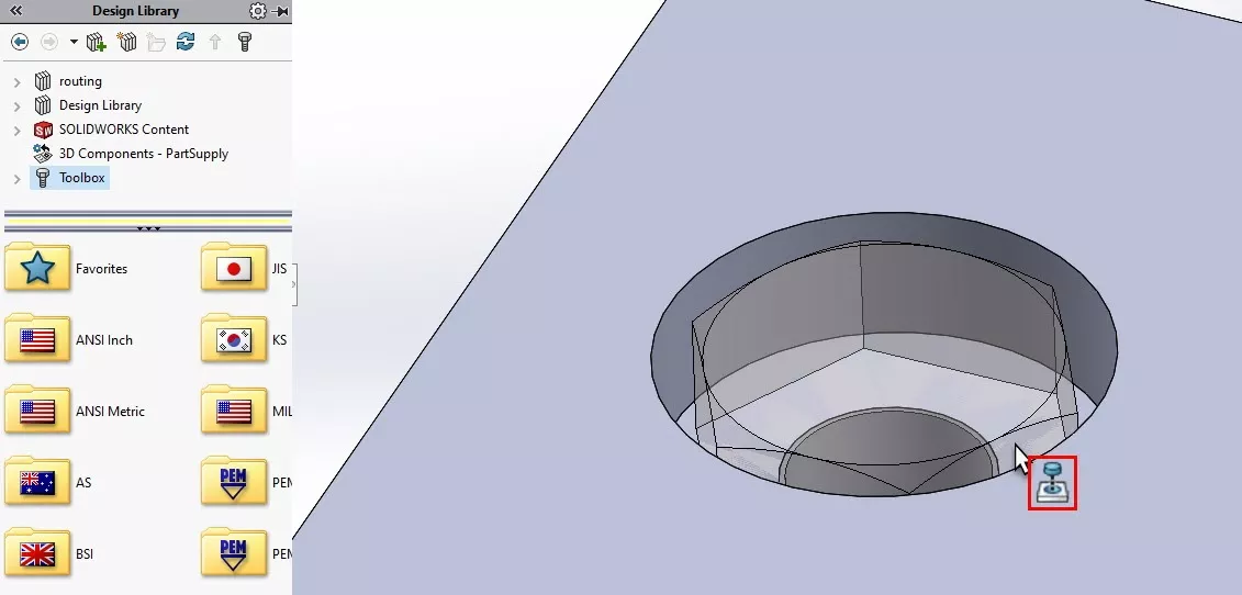
The drag & drop functionality is the most common use in toolbox. To access this functionality the user will have to choose the design library icon. The icon is modeled after a collection of books, like what would be found in a ‘library’. Once this is selected a flyout for the design library will appear on the right side of the user interface.
An example of the toolbox section of the design library is on the right. Once the toolbox is selected it will display folders for the various standards and components available to the user. These can be used to select the desired hardware. Alternately the triangle icon next to “Toolbox” in the design library can be used to open drop-down options, this is a second way to navigate to desired components.
Once hardware components are displayed on the right they can be dragged into the modeling window. Hole wizard and toolbox are built to work together, when a toolbox component is dragged over a hole wizard hole it should match the size of the hole as well as display the insert icon (shown left). Once this icon is seen releasing the left mouse button will insert the hardware component into the assembly. It can then be sized using the toolbox properties that’ll appear on the left.
The toolbox insert window is automatically pinned allowing the user to insert duplicate pieces of hardware quickly. Once the size has been chosen the user can select any other hole wizard hole and can continue inserting hardware without reselecting size.
Toolbox Properties in Bill Of Material
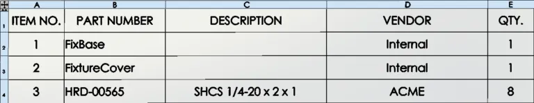
One powerful part of the toolbox is that properties can be associated with the hardware and this information can be automatically added to Bills of material (BOMs). By default, the part number and description in the toolbox will be added to the standard BOM (image below). To add custom properties a column will need to be added to the BOM. Once added the user can select the custom property that should be displayed. In this example, a custom property named “VENDOR” was added to the BOM. The property in Toolbox should match the custom property used in other components in the assembly, this should minimize the number of unpopulated boxes.
Editor's Note: This article was originally published in July 2020 and has been updated for accuracy and comprehensiveness.

SOLIDWORKS CAD Cheat Sheet
Our SOLIDWORKS CAD Cheat Sheet, featuring over 90 tips and tricks, will help speed up your process.
Related Articles
SOLIDWORKS Toolbox Default Search Location Option
SOLIDWORKS Toolbox Performance Optimization

About Cody Salyer
Cody is an Application Engineer based out of the beautiful Salt Lake valley. He’s been with GoEngineer since 2016 supporting not only SOLIDWORKS but also Simulation and PDM as well. His background includes mechatronics and automation, where he has worked to develop automated systems to help remove or disconnect people from dangerous tasks.
Get our wide array of technical resources delivered right to your inbox.
Unsubscribe at any time.