Meshing issues with SOLIDWORKS Simulation
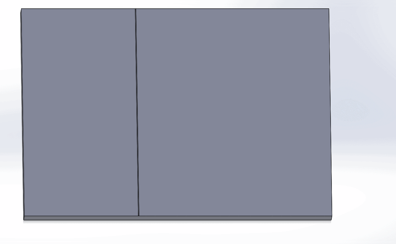
A good mesh can converge the results quickly. On the other hand, a bad mesh can ruin your day. If you are having mesh there are a few things you need to consider. Let’s first look at meshing parts. I have put a .5 mm split on a face and then tried to mesh it.
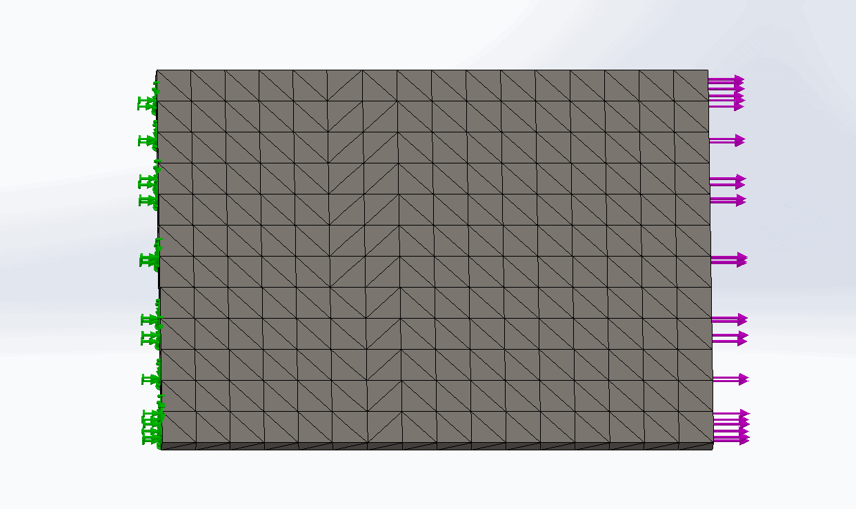
This is with a 13 mm mesh.
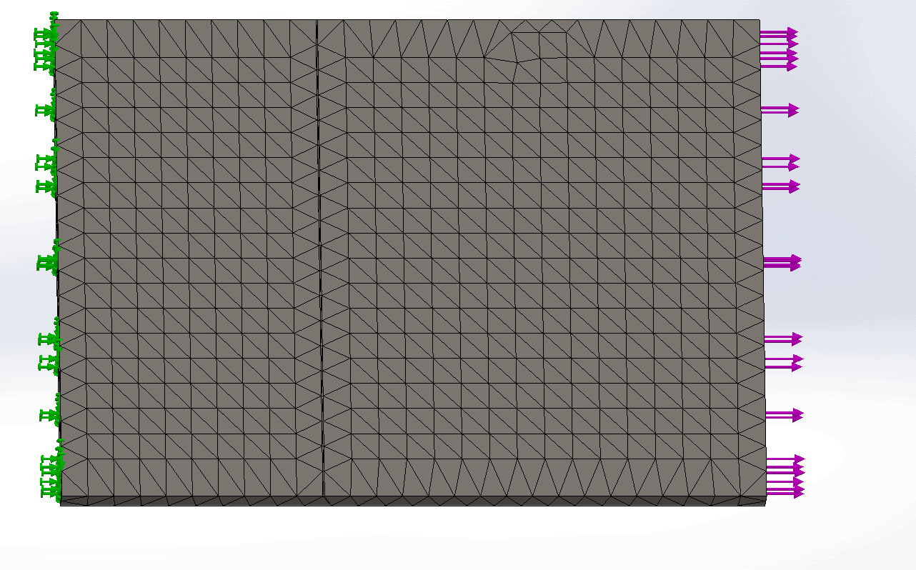
This is with an 8 mm mesh.
Notice that the split face does not get included in the mesh. When the element size is large enough to ignore the split face the results will be crude. The natural reaction is to reduce the element size so that all the smaller geometry can be included in the analysis. This may cause the calculation time to take much longer. My recommendation is to reduce the complexities in the geometry if at all possible. Then use shell or beam elements where you can.
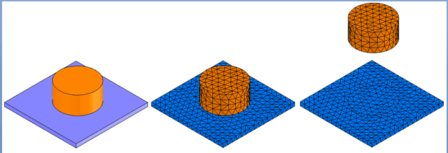
At the assembly level it can be more complex. The first step should be to make sure you don’t have interference. Of course, you should follow the procedure for all parts that are in your assembly so contacts can be assigned quickly. There will be times when you do want the complex contacts to occur, for instance, line and point contacts. The mesh can fail to do the bonding of those types of contacts.
If this is the case then do the following:
-Change the global contact to Bonded- incompatible to see if assembly meshes completely.
-Use no penetration if it applies to that specific location where the mesh is failing.
-If you need to bond and need a compatible mesh to attain convergence then try to reposition the parts so they can be meshed.
-You can also control the shape of the mesh by splitting the face where the contact is going to happen.

 Blog
Blog 


