SOLIDWORKS Assembly Validation Tools – Part 4 - Hole Alignment
Every engineer loves to hear about ways to be more productive, save time, and avoid rework costs. Well, SOLIDWORKS has a great tool to help you do all of these by ensuring that your designs will assemble correctly. You can very easily check that all your mating parts, mounting holes, and fasteners are aligned. This ability to check for hole misalignment during the design phase will speed up the overall product development process. Before a part is sent to manufacturing, use SOLIDWORKS Hole Alignment to confirm hole alignment between mating components in your assembly designs to ensure proper fit. SOLIDWORKS Hole Alignment checks assemblies for misaligned holes. It checks alignment of Hole Wizard holes, simple holes, and cylindrical cut features. This alignment applies both to components to be assembled and those that hold the design together (screws, bolts, pins, etc.). The Hole Alignment tool is especially good for confirming complex linear and circular hole patterns.
Note: Hole Alignment is feature-based. Alignment is checked for Hole Wizard holes, simple holes, and cylindrical cut features. Hole Alignment does not recognize holes in derived or imported bodies, or multi-boundary extrudes.
Finding Misaligned Holes
Use Hole Alignment to check assemblies for misaligned holes.
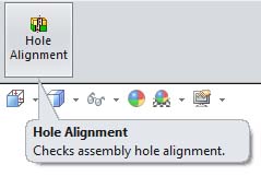
To start the command, click Tools – Hole Alignment or you can add the Hole Alignment button to the Assembly toolbar.
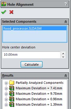
You can select what components to check in the Hole Alignment PropertyManager. By default, the top-level assembly appears unless you pre-select other components. When you check an assembly for hole alignment, all of its components are checked. If you select two or more components, only the misalignments between holes in the selected components are reported.
SOLIDWORKS allows you to set a maximum acceptable Hole center deviation. This value is used to specify the maximum distance between centers for sets of holes to check. For example, if you specify 10.00mm, then sets of holes whose centers are within 10.00mm of each other, but not aligned, are listed under Results.
To get the results, simply click Calculate and SOLIDWORKS will check for hole alignment.
Supported Hole Types
Hole alignment is feature-based. Alignment is checked for Hole Wizard holes, simple holes, and cylindrical cut features. Hole alignment does not recognize holes in imported parts and bodies or multi-boundary extrudes. However, holes you add to imported or derived parts are recognized because they are separate features.
Derived parts and bodies that are created using Move/Copy Body, Split Part, Pattern Body, or Insert Part are also not supported.
Hole Alignment does recognize holes created by mirroring features, faces, or bodies in a part. Hole Alignment also recognizes holes created when you use Insert > Mirror Part or Insert > Mirror Components to create an opposite-hand version of a part that contains valid holes.
Hole Alignment Results
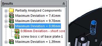
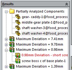
Hole Alignment displays the detected misalignments and reports the maximum deviation between centers for each set of misaligned holes. The Results are interactive. So, if you click the items in the Hole Alignment PropertyManager, the results are highlighted in the graphics area.
If you expand the item, you can see the individual holes involved in the misalignment listed.
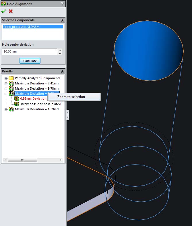
You also have the ability to right-click on an item and pick Zoom to selection.
Note that in my example, Hole Alignment recognizes some holes in the assembly, but since it detected that it could not analyze a portion of the assembly, SOLIDWORKS lists the information in the folder named Partially Analyzed Components.
For the Partially Analyzed Components, you have to manually examine the part and related components for misaligned holes.
For a brief video demonstration of the Hole Alignment tool, please click here.
We hope this has given you a better understanding of the capability available in the Hole Alignment command. Please check back for the rest of the series as we continue to take a deep dive into the SOLIDWORKS assembly validation tools that are available and how they work. Please check back to the CATI Blog as the Dedicated Support Team will continue posting new series of articles every month that go further into the details of many of the SOLIDWORKS tools. All of these articles will be stored in the category of Daily Dose…..of SOLIDWORKS Support and links to each article with their release date are listed below:
- SOLIDWORKS Assembly Validation Tools – Part1 (Bryan Pawlak 7/16/14)
- SOLIDWORKS Assembly Validation Tools – Part2 (John Van Engen 7/18/14)
- SOLIDWORKS Assembly Validation Tools – Part3 (Blake Cokinis 7/21/14)
- SOLIDWORKS Assembly Validation Tools – Part4 (Neil Bucalo 7/23/14)
Neil Bucalo, CSWP, CSWS-MD
Computer Aided Technology, Inc.

 Blog
Blog 