Bounding Boxes are not for Weldments alone!!
SOLIDWORKS 2013 introduced the “Bounding Box” feature in Weldments. A bounding box is a 3D sketch that defines the smallest box in which the part fits.
The truth is, you can use the bounding box for ANY kind of part! With this feature, you no longer have to manually find the stock size for parts. There are only a few easy steps to create the Bounding Box feature.
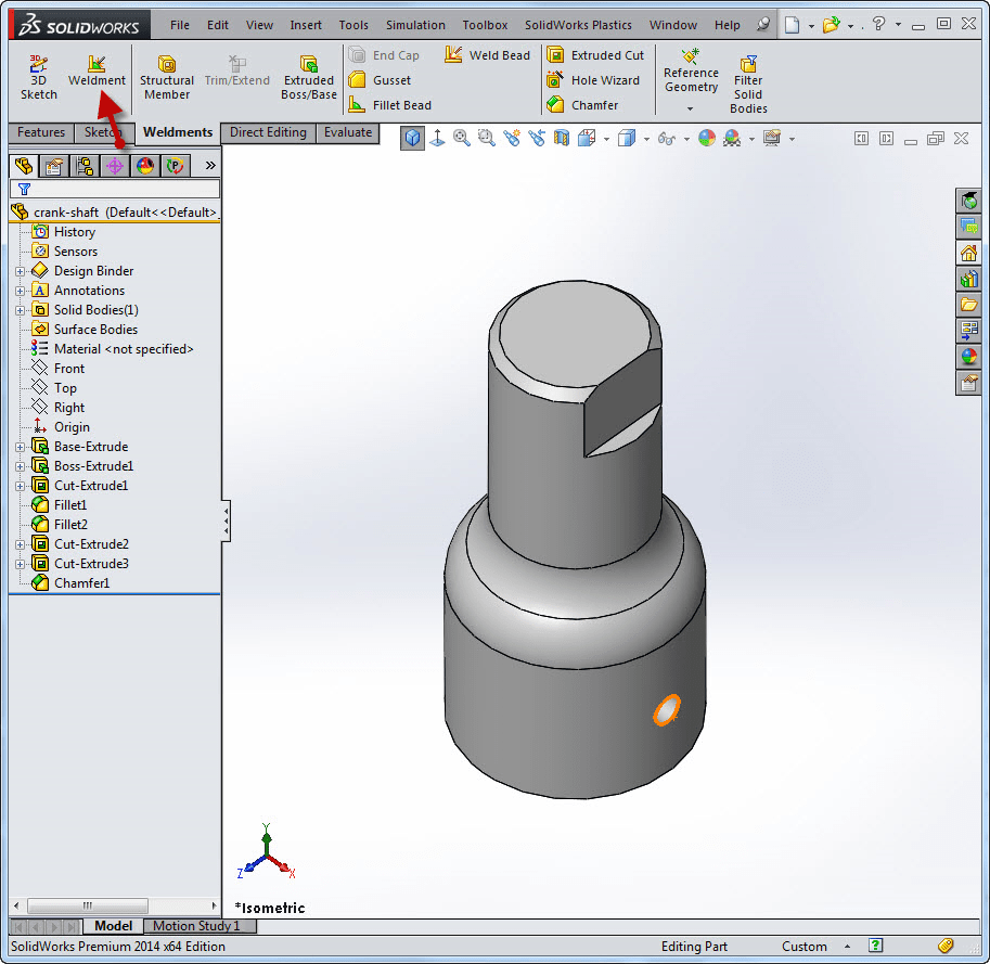
When the part is modeled (or imported), turn the part into a Weldment by using the Insert > Weldment feature in the Weldment Command Manager. (If the Weldment Command Manager tab is not visible, Right Mouse click on any of the command manager tabs and check Weldment on.)
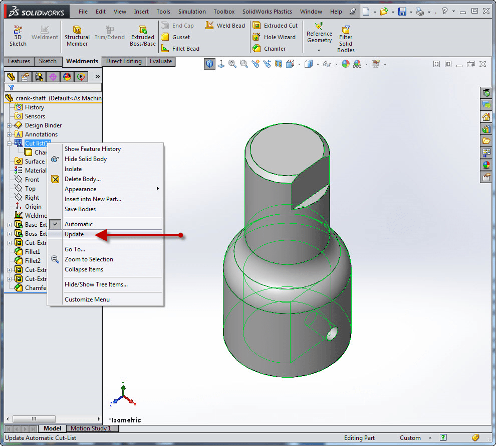
This will change the solid body folder into a cut list folder. Right Mouse click the Cut List item in the Feature Tree and choose Update.
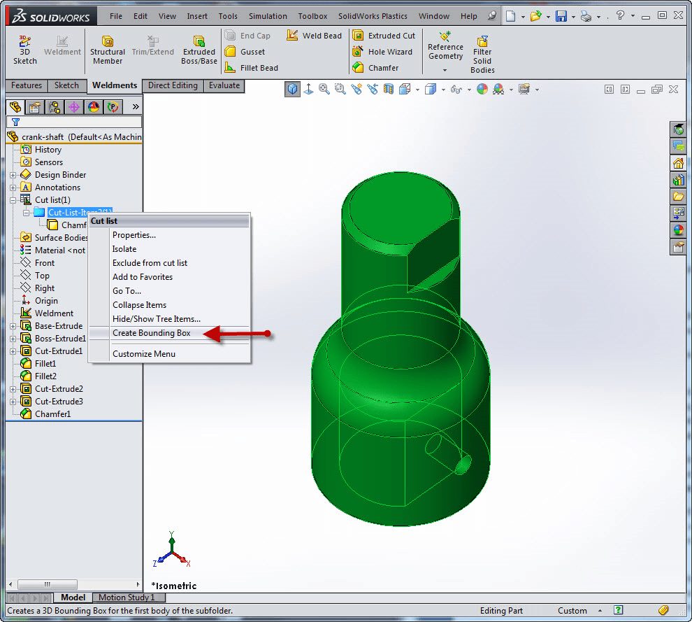
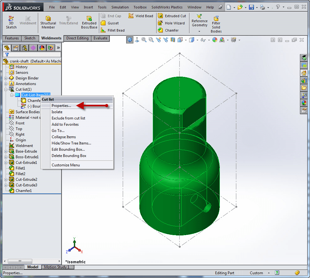
Expand the Cut List item in the tree and Right Mouse Click on the Cut List Item 1 folder and choose Create Bounding Box.
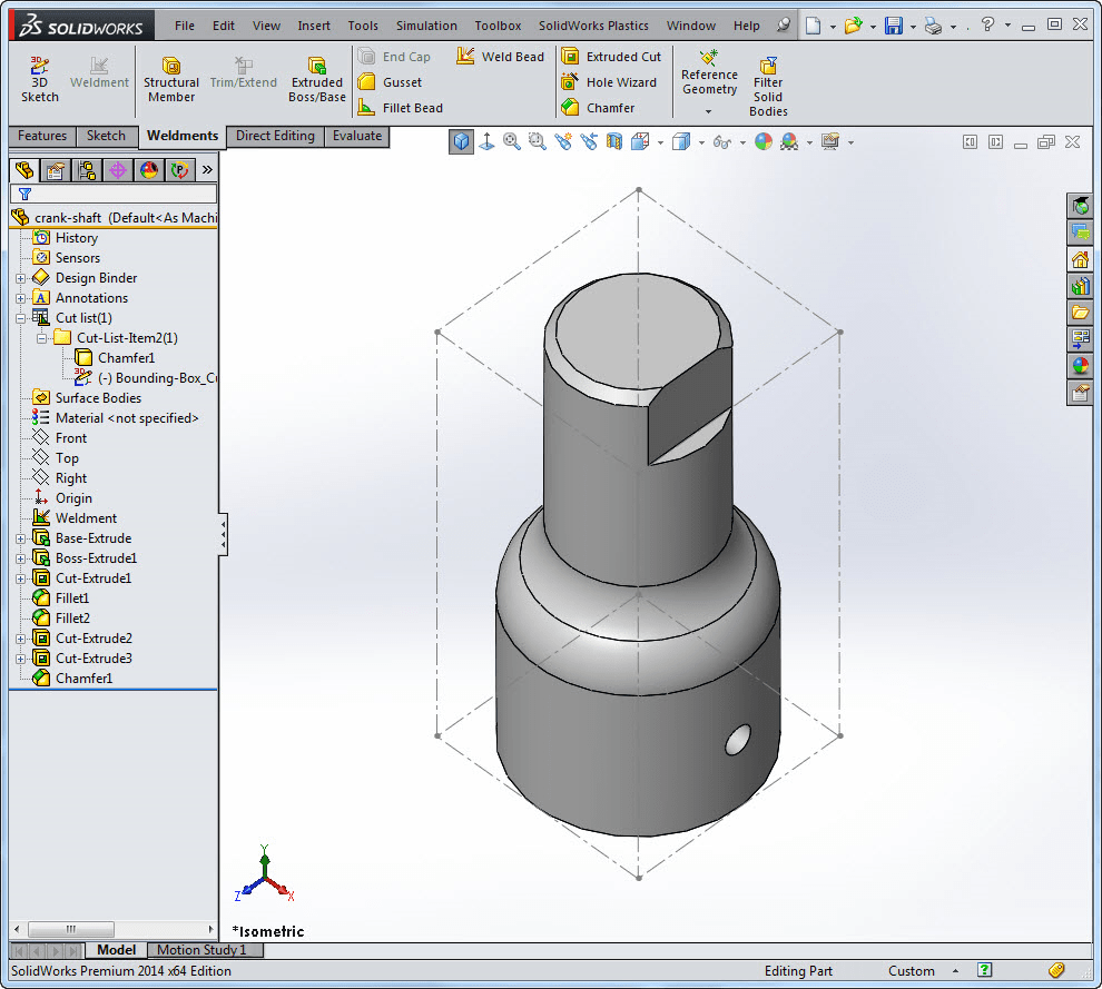
If you want to see the 3D bounding box that was created, click Show the 3D sketch that was created. By default, the Bounding Box orientation is on the X-Y plane (unless you preselect a plane or planar face). If the Bounding Box is not oriented in the manner you would like, a right mouse click will allow you to Edit Bounding Box.
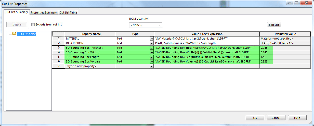
Reference dimensions can be added to the bounding box if you want to show actual dimensions or Right Mouse click on the Cut list item1 folder and choose Properties. These properties will show you Thickness, length, width and volume of the 3D bounding box.
With SOLIDWORKS parametric capabilities, any changes to the model will update the bounding box too.
This is a great feature that can save you a lot of time and is not just for weldments!
Judy Marlo
CATI Application Engineer

 Blog
Blog 