Using 3D Interconnect with SOLIDWORKS CAM & CAMWorks
Importing files can be a hassle in any CAD or CAE environment. Different vendors utilize different kernels, and while STEP files are nice, everyone has encountered at least one that didn’t quite behave as expected.
Starting in SOLIDWORKS 2017, Dassault Systemes introduced 3D Interconnect, a “CAD Translator” that can take native CAD files from other vendors. You can see a video here describing the capability, but in short it provides the following benefits:
- Users can now import native CAD files from a variety of software with no loss in fidelity.
- Those CAD files maintain an associative link – if the imported file gets updated, those updates will reflect in SOLIDWORKS.
- These CAD files can be utilized in any SOLIDWORKS environment, as we will discuss here.
The most common use case is to include non-native components in Assemblies, however other environments and tools such as SOLIDWORKS CAM & CAMWorks will utilize these imported files just fine.
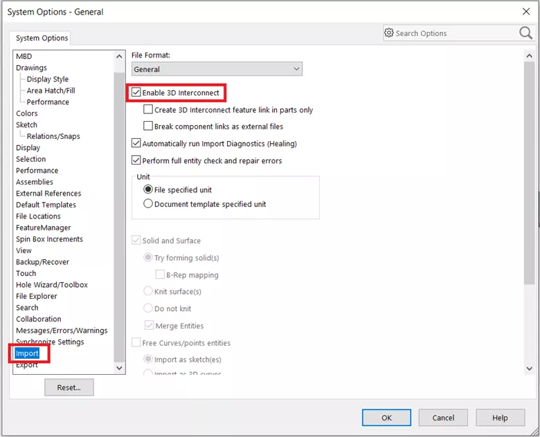
The first step is to go to your System Settings or Tools > Options… and checking that your import settings are set as such:
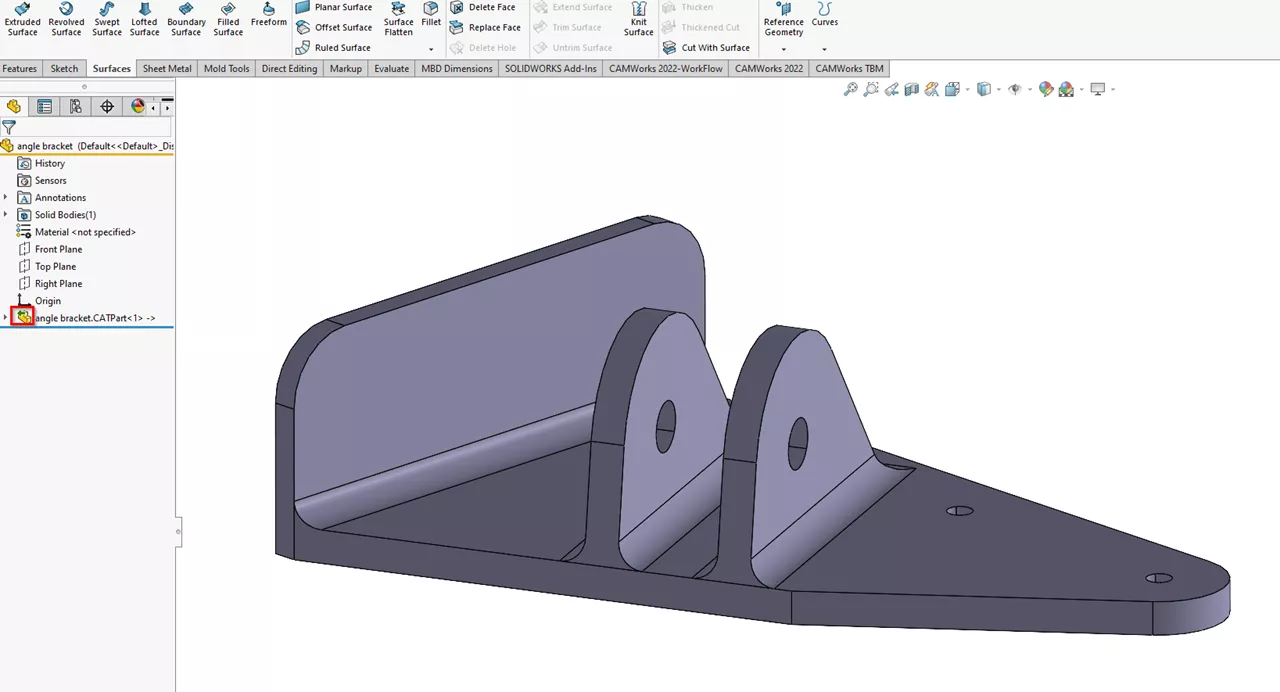
In this example, the file I’m working with is a part made in CATIA. Although CATIA and SOLIDWORKS are both Dassault Systemes products, CATIA uses the CATIA graphics modeling kernel (CGM), where SOLIDWORKS utilizes the Parasolid kernel. As a side note, the 3D Interconnect tool supersedes the now-defunct CATIA V5 SOLIDWORKS Translator.
Using the standard File > Open command, I have imported a .CATpart file. The highlighted icon indicates that the 3D Interconnect functionality is working.
From here, I will proceed with my usual CAMWorks setup to prepare this file for milling. I’ll use Automatic Feature Recognition (AFR) to get going.
For a more detailed walkthrough on setting up a part for CAMWorks/SOLIDWORKS CAM, please consult this video.
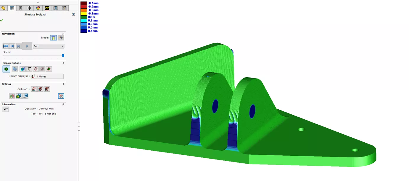
Using AFR and a few tweaks to the Operation Plan, we are able to generate and simulate our part! When I create the second setup, I’ll be able to clean up the fins and drill the through holes easily.
CAMWorks and SOLIDWORKS CAM are substantial automation powerhouses – each time you fire up the software, it’s designed to reduce the number of clicks from the last time you launched it.
Adding in the power of 3D Interconnect in SOLIDWORKS Premium, users can maintain a complete source of truth across a variety of vendors from design all the way to manufacture.
I hope you found this article for using 3D Interconnect with SOLIDWORKS CAM & CAMWorks helpful. To learn more, check out the additional articles listed below.
Related Articles
STEP and IGES Files – Avoiding Import Issues
SOLIDWORKS 3D Interconnect 2019: Export Revit Files & More
Comparing SOLIDWORKS Packages: Features in Standard, Professional, and Premium
How to Set Up a Firewall Exception for CAMWorks Teksoft.exe

About Mike Britton
Mike Britton is a SOLIDWORKS Application Engineer based out of Chicago, Illinois. In addition to his work with GoEngineer, Mike is a competitor on Discovery Channel's BattleBots and volunteers with his childhood summer camp & local makerspaces.
Get our wide array of technical resources delivered right to your inbox.
Unsubscribe at any time.