SOLIDWORKS Then and Now: 2d to 3d
In SOLIDWORKS 2001 plus we introduced 2d to 3d functionality. Here is a quick run through on how it works. The following is an updated version of the “what’s new” document from September 2001.
The 2D to 3D tools facilitate converting a single sketch into a set of separate sketches, each positioned and oriented as required to create a 3D model. The tools fold up the 2D sketch as if it were a piece of paper. When you import a drawing for conversion, you specify which portions of the drawing are the sketches for the front view, right view, and so on. You can also create auxiliary sketches that are not parallel to the principal view planes. Hidden lines, which are dashed lines in an imported drawing, are construction lines.
You use the 2D to 3D tools to align sketches with each other, with edges and vertices of a part, or with the origin. You can align sketches before you use them to create a part, or you can align sketches during the part construction process. The following tools are used to convert a single flat sketch into separate sketches in their correct position and orientation. For example, you select all the sketch segments that belong to the top view and click the Top tool to create a new sketch in the top view orientation.
1.Go to File, Open.
2.Change the file type to DWG or DXF
3.Click Open

4.Select the Import to a new part as 2D Sketch

5.Set Units of import accordingly
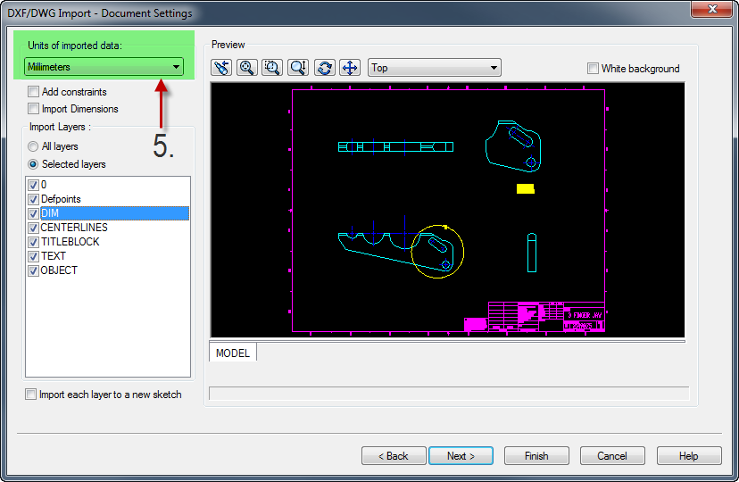
6.Customize layer import, turn off unneeded detail
7.Click finish

8.Set the origin for the sketch by selecting a single point on the sketch and clicking on align sketch icon.

9.Remove the detail view by box selecting around it and pressing the delete key on your keyboard.

10.Now it’s time to split out the views. Box select the front view and click the front view icon on the 2d to 3d toolbar

11.Now repeat this process for the Top and Right side views.
12.Now that views are folded we will do a little alignment with the align command on the 2d to 3d toolbar.
13.You will first select the line segment that will be moving from the top view. Second you will select a segment on the front view so you can align the top view segment to it. Then click the align sketch icon.

14.Repeat this procedure for the Right view sketch and front plane. Select an segment on the right view sketch first followed by the front view sketch.
15.Now extrude the front view sketch.
16.Change the End Condition to the up to vertex option and select a vertex on top value that corresponds to the depth you need.
17.(optional) Click in the selected contours dialog and add the selections for the pivot hole and slot to remove them from the extruded area.

18.Let’s remove the finger tips by using the right view sketch as a cutting tool. Start the cut extrude command and change the End Condition to Through All, and finish the command.
19.By checking on the Flip side to cut. And click OK. Enjoy you 3d model.

Bob McGaughey, CSWE
CATI