When creating a SOLIDWORKS sheet metal flat pattern drawing view, why is the view not flattened?
Even though SOLIDWORKS has greatly enhanced the sheet metal tools, we still get the question asked: When creating a flat pattern drawing view, why is the view is not flattened? To understand this better, let's go through the steps of what is suppose to happen when you create a new SOLIDWORKS sheet metal flattened view.
1. Create a drawing from a SOLIDWORKS sheet metal part document.
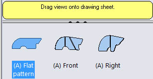
2. Insert the flat pattern view.
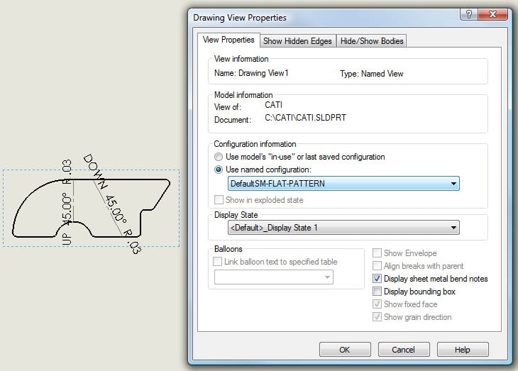
3. Right Click on the new drawing view and pick Properties. As you can see in the Drawing View Properties dialog box, SOLIDWORKS automatically creates a configuration name DefaultSM-FLAT-PATTERN and sets the drawing view to use this named configuration.
This is what may be confusing to some. Since SOLIDWORKS automatically creates this new configruation in the part document, whatever is shown in the DefaultSM-FLAT-PATTERN configuration is what will be shown in the drawing. Just because the name of the configuration says FLAT-PATTERN does not mean that SOLIDWORKS knows to stay that way. A lot of the times, the DefaultSM-FLAT-PATTERN configuration is not in the flattened state. This can easily be done if the user does not realize what configuration is active. A quick example:
1. Switch over to the part document.
2. Set the active configuration to DefaultSM-FLAT-PATTERN.
3. Click the Flatten button in the Sheet Metal toolbar so that the part bends back up.
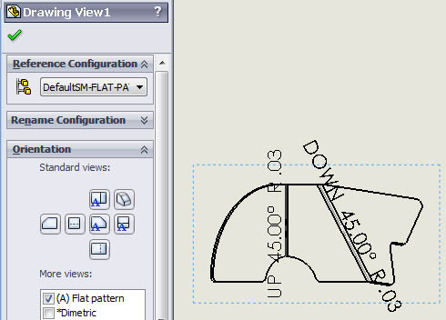
4. Switch back to the drawing. As you can see, the view is still set to the Flat pattern Orientation in the Drawing View PropertyManager, but the drawing view is no longer flattened.
So far, this has resolved the issue most of time by making sure that the DefaultSM-FLAT-PATTERN configuration of the part document is in the flattened state. I did have one other issue where the user's document template already had the DefaultSM-FLAT-PATTERN configuration. So, when the drawing view was inserted, SOLIDWORKS could not automatically create the configuration and set the sheet metal state to flattened. The solution was to open a new part document, delete the DefaultSM-FLAT-PATTERN configuration, and resave the document template. The next time the user created a sheet metal part and then created the flattened drawing view, it worked correctly.
Neil Bucalo
Technical Analyst
Computer Aided Technology, Inc.

 Blog
Blog 

