Rolled Edge Flanges
A common feature in the sheet metal industry are rolled edge flanges on a cylindrical parts. With all the great sheet metal tools that SOLIDWORKS has to offer, that is one area the software has strugggled in the past. SOLIDWORKS has never had the capabilitys to create a part as such and still be able to create a flat pattern from it. With the introduction of SOLIDWORKS 2012, that has all changed. SOLIDWORKS now has a new feature available in sheet metal that will allow you to create “Rolled Edge Flanges”. Its called “Swept Flange”. With this new feature, you now have the ability to create complex sheet metal parts and create flat patterns that go along with them.
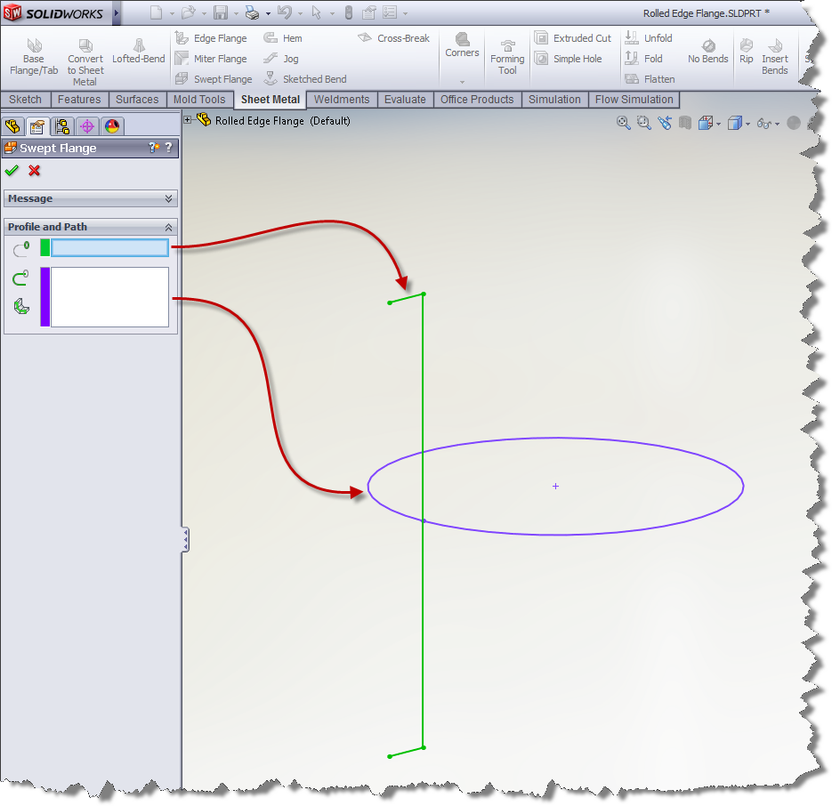
Take a look at the example below…
Just like any sweep feature, you need to create both a profile and a path sketch (Note: with a sheet metal part, the path needs to be an open contour). Once you have your sketches, simply utilize this new swept flange feature located in the sheet metal features…
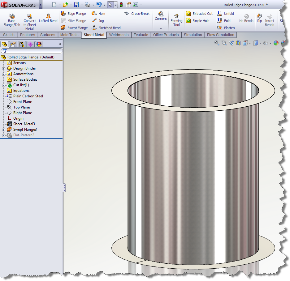
The results are just as you would expect…
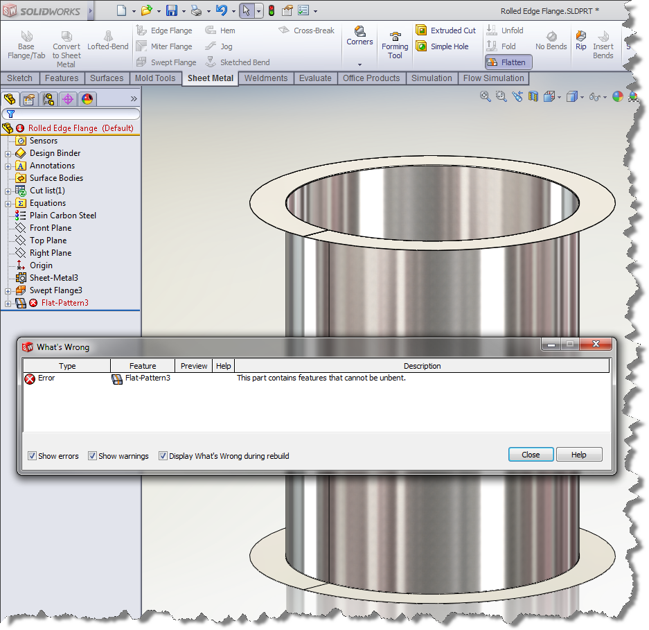
However, as good as this new swept flange feature is, there is a slight problem when you go to show the flat pattern. You will get an error stating that this part cannot be unbent…
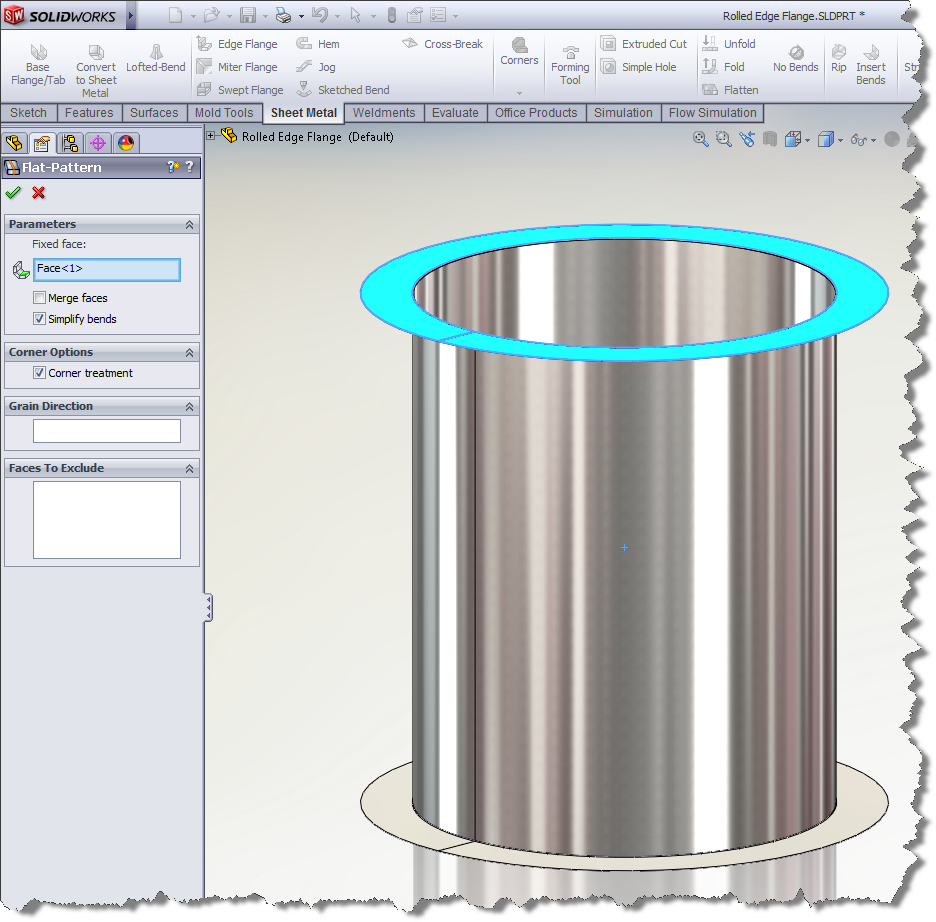
Fortunately, there is a workaround. The problem isn’t necessarily a problem with the geometry, but rather a problem with what SOLIDWORKS thinks should be the fixed face/edge. If you edit the flat pattern feature, you can clearly see what face SOLIDWORKS is trying to keep fixed…
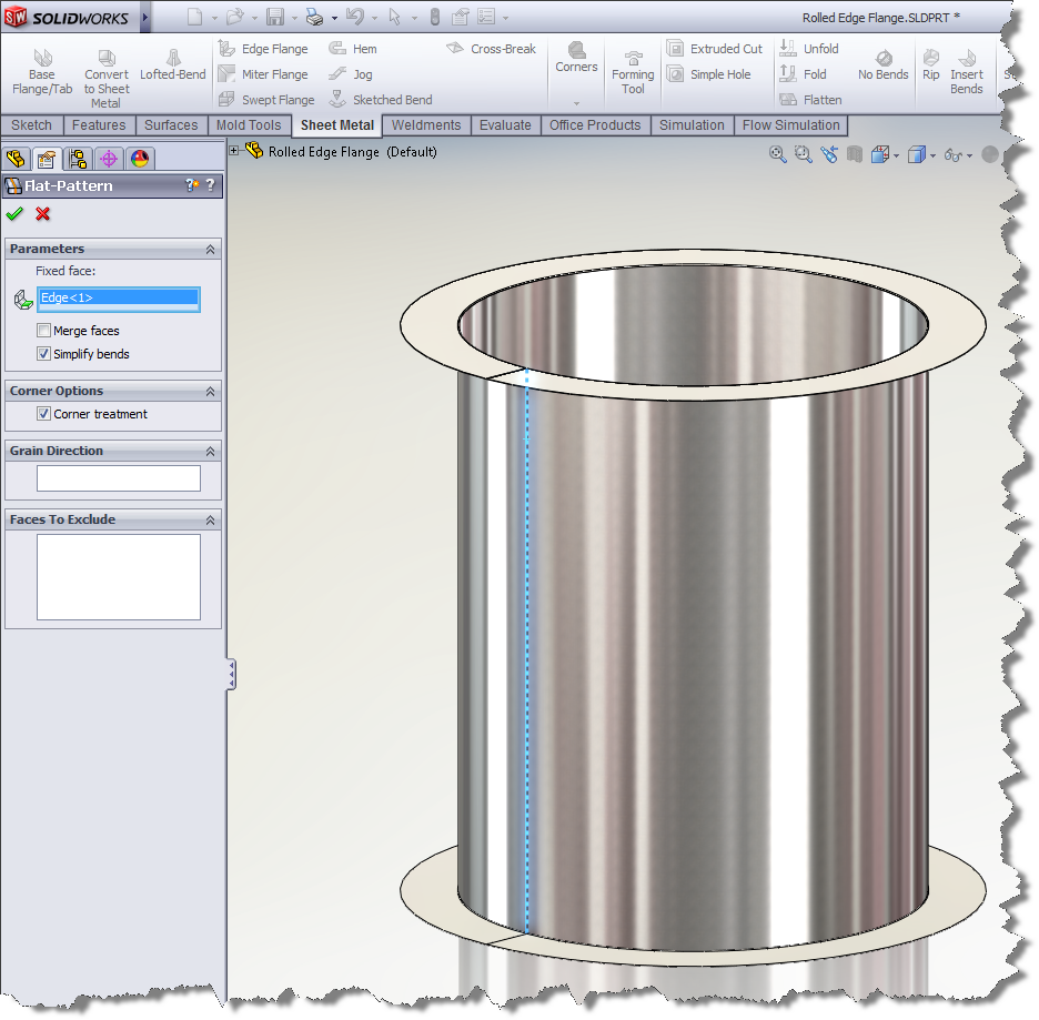
To get this flat pattern to work correctly, you will need to select an edge to remain fixed; Just as you would if this was a rolled cylinder without the flanges…
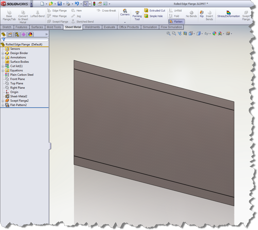
Once you tell SOLIDWORKS what edge is to be fixed, the flat pattern will work as expected…
SOLIDWORKS does have a handful of SPRs out there that address this very issue on similar parts as you see here in this example. So if you run into a similar issue, look to see what SOLIDWORKS is trying to keep fixed when flattening the part. Most likely, this workaround will resolve the issue.
Even with the workaround, the addition of this new “Swept Flange” feature greatly enhances the sheet metal capabilities in SolidWorks. You can now create more complex sheet metal parts than ever before.
Nathan Brunner, CSWP
Technical Analyst
Computer Aided Technology, Inc.

 Blog
Blog 
